
 English
 中文
中文 العربية
 español
Introduction
AI is changing the thermal math inside data centers. A room built around ~10–15 kW racks can be asked—almost overnight—to host 40–120+ kW AI racks where the limiting factor isn’t nameplate cooling capacity on paper, but the ability to move heat out of the rack reliably, repeatably, and without operational drama.
That raises the core question operators are dealing with right now: can a traditional air-cooled site adapt without a full rebuild?
For most estates, the practical answer is yes—but rarely by “doubling down” on air alone. Survivability comes from hybrid AI GPU rack cooling: keep air efficient for general IT, and add liquid where physics and rack packaging demand it.
In this article you’ll get:
-
The density thresholds that usually force the cooling conversation to change
-
Retrofit paths that don’t require betting the entire site on a single cutover
-
How PUE, WUE, uptime risk, and TCO typically move when you add liquid cooling
-
The operational controls (telemetry, leak detection, commissioning discipline) that keep hybrid deployments boring—in the best way
Density Realities: Air vs. Liquid for AI GPU Rack Cooling
Air Cooling Limits
Air cooling doesn’t “stop working” at a precise kW/rack value. It fails in more operator-specific ways:
-
Airflow delivery becomes the constraint: you can’t always push enough CFM through a dense rack without unacceptable pressure drop.
-
Hotspot control becomes fragile: minor bypass, blanking errors, or containment gaps turn into GPU throttling events.
-
Fan power and noise climb: server fans ramp hard when inlet conditions drift, and that power shows up in both electrical and thermal budgets.
-
The room becomes harder to operate: every maintenance action (opening doors, changing cable routes, moving floor tiles) has thermal consequences.
Industry surveys remind us why this feels sudden: many facilities still run comparatively modest densities. In Uptime Institute’s 2020 survey write-up, the most common average rack density was 5–9 kW, with relatively limited broad deployment above 20 kW (Uptime Institute, “Rack density is rising”). AI changes the distribution by creating “islands” of extreme density inside otherwise conventional rooms.
A useful rule-of-thumb from operators and colo providers is that traditional air designs become increasingly inefficient and operationally risky once racks push into the ~15–20 kW band (Flexential on air cooling limits and liquid options). Past that point, “more air” often means more complexity—and complexity is where uptime risk hides.
Liquid Cooling Bands
Liquid cooling isn’t one thing. It’s a spectrum of approaches with different retrofit friction:
-
Rear-door heat exchangers (RDHx): capture exhaust heat at the rack boundary. This is often the lowest-disruption bridge when you want to keep servers largely unchanged.
-
Direct-to-chip (D2C): bring liquid to cold plates on GPUs/CPUs (and sometimes memory/VRMs). This is where many AI deployments land because it targets the hottest components directly.
-
Immersion: put hardware in dielectric fluid for extreme densities and certain operational models.
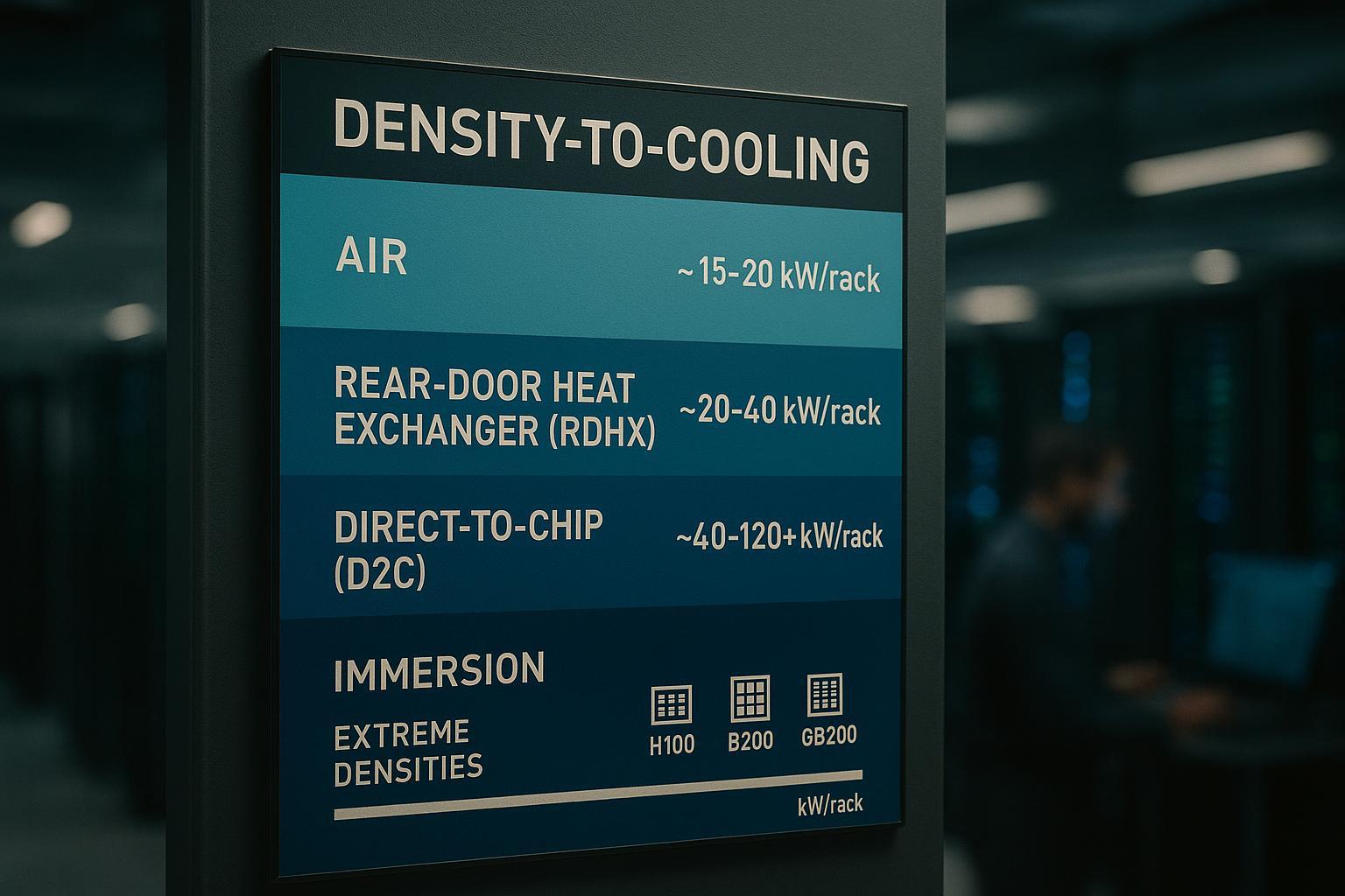
For a practical decision framework, many operators treat these as density bands:
-
Air: best fit up to ~15–20 kW/rack (with strong containment and airflow hygiene)
-
RDHx: often a bridge in the ~20–40 kW/rack band (especially for brownfield upgrades)
-
D2C: common once you’re planning ~40–120+ kW/rack pods
-
Immersion: an option for the far end of density (or for specific fleet/maintenance models)
These ranges aren’t universal laws—but they’re helpful starting points for scoping and procurement.
Mapping GPUs to kW/rack
For operators, the key isn’t the GPU brand label—it’s how GPU packaging and cluster architecture concentrate heat. Modern AI racks tend to combine:
-
high silicon power density (GPUs + CPUs)
-
higher average utilization (training and some inference clusters run “hot” for long periods)
-
tight coupling to network and power delivery that reduces your freedom to spread load
So instead of asking, “Can we cool an H100 rack with air?”, the more practical question is: what rack power band does this cluster design land in, and what cooling strategy keeps performance stable under real operating conditions?
At a high level:
-
Many “GPU-class” builds quickly outgrow pure air assumptions.
-
As designs move toward rack-scale integration (more accelerators per rack), D2C becomes less of an optimization and more of an enabling constraint.
Key Takeaway: If your AI plan puts you in the 40–80 kW/rack band, treat liquid cooling as a program (loops, controls, procedures)—not a piece of hardware you bolt on later.
Retrofit Playbooks for Traditional Sites
Phased Upgrades (RDHx → D2C AI Pods)
A survivable retrofit pattern looks less like “convert the whole building” and more like segmenting the estate by load type:
-
Harden air for general IT
-
Fix containment, blanking, bypass air, and return-air short-circuiting.
-
Rebalance CRAC/CRAH operation and validate actual delivered airflow by row.
-
Goal: keep low-to-moderate density workloads efficient and predictable.
-
-
Use RDHx as a bridge for the first density jump
-
RDHx can remove a large fraction of rack heat while preserving a mostly air-cooled room.
-
This is useful when you need density relief quickly without changing server SKUs.
-
Operationally, you’re introducing water near racks—but still not inside servers.
-
-
Stand up a dedicated D2C “AI pod” for 40–80 kW/rack
-
Treat it as a contained zone: defined racks, defined manifolds, defined CDU capacity, defined monitoring points.
-
Keep it modular so it can scale pod-by-pod without rewriting the whole facility.
-
-
Scale based on measured KPIs, not hopes
-
Expand only when telemetry shows stable thermal performance, clean alarm behavior, and maintainable procedures.
-
This sequencing matters because it keeps a rollback path: air continues to carry the estate while the liquid program earns trust.
Hydraulics, CDUs, and Loops
Once you cross into D2C territory, “cooling” becomes as much about fluid engineering and controls as it is about heat exchangers.
A retrofit-friendly mental model is three layers:
-
Facility loop (building chilled water or warm-water loop, plus heat rejection)
-
CDU layer (the bridge between facility water and the technology coolant loop)
-
Technology coolant loop (to rack manifolds → to cold plates → back)
A CDU is typically the interface point that circulates and regulates coolant for the IT side while exchanging heat to the facility side. It’s also where you want concentrated monitoring and protection. Coolnet’s overview frames the CDU as the “hub” that manages temperature, pressure, and flow between IT equipment and the facility loop (Coolnet’s CDU overview).
For phased D2C retrofits in the 40–80 kW/rack band, keep the design operator-friendly:
-
Isolation everywhere you’ll service: valves that let you isolate a rack, a manifold branch, or a CDU without draining the entire pod.
-
Short, protected hose runs: minimize fittings and elbows; every connector is a potential leak point.
-
Dew-point discipline: either keep supply temperatures safely above room dew point, or treat humidity control and condensation prevention as a first-class requirement.
-
Flow and pressure stability: cold plates care about differential pressure and minimum flows; validate in commissioning, not during production.
Where Coolnet can fit into a non-promotional retrofit narrative is as an example of integrated building blocks: an integrated CDU plus monitoring/telemetry simplifies phased expansion because each new pod can inherit a consistent points list and alarm model (temperature, flow, differential pressure, pump status, and fault states). Coolnet’s high-density discussion emphasizes CDU telemetry such as supply/return temperatures, flow, ΔP, pump state, and alarms, and the need to monitor dew point to manage condensation risk (Coolnet on high-density rack cooling and telemetry).
Site Constraints and Cutover Windows
The best retrofit plan is the one that admits constraints early:
-
Space and access: RDHx adds depth and weight; D2C adds manifolds, hose routing, and CDU footprints.
-
Raised floor vs slab: underfloor pipes compete with airflow; overhead routes raise containment and drip-management questions.
-
Heat rejection reality: if the building loop can’t carry the new load, the AI pod becomes a stranded asset.
-
Downtime windows: tie each phase to an MOP with a rollback path.
For cutovers, treat “parallel run” as the default posture:
-
Commission the liquid loop and alarm chain while the air system remains your safety net.
-
Move a small number of racks first, prove stability under normal operation and under maintenance actions.
Warning: The most expensive outcome in a brownfield liquid retrofit isn’t a pump failure—it’s discovering during go-live that your monitoring can’t distinguish a nuisance alarm from a rack-at-risk event.
PUE, WUE, and Sustainability
Energy Efficiency and PUE Targets
High-density air solutions often improve peak capacity but can push up operational overhead: more fan power, more air movement, more control effort.
Liquid cooling can reduce that overhead by moving more heat with less parasitic energy. LBNL’s Center of Expertise summarizes why: liquids have far higher heat capacity than air, so you can remove large thermal loads with much lower volumetric flow (LBNL on liquid cooling).
That said, PUE outcomes depend on architecture:
-
If liquid enables warmer coolant temperatures and more hours of economization, PUE can improve.
-
If liquid is added but the heat rejection layer stays inefficient (or controls are poorly tuned), the theoretical benefit erodes.
So the target shouldn’t be “hit a magic PUE number.” It should be: reduce cooling overhead without increasing operational fragility, while protecting performance.
Water‑Wise Designs (Closed Loops, Dry Coolers)
Water is now a design constraint, not a footnote.
A practical water-wise direction for many operators is:
-
closed-loop liquid systems on the technology side
-
warm-water operation when feasible (supports more dry-cooler hours)
-
dry coolers / fluid coolers as the default heat rejection path where water constraints are tight
The broader industry is increasingly explicit about the energy-water trade: Google describes its approach as balancing energy and water impacts depending on climate and site constraints (Google Data Centers on water). Microsoft has also discussed designs intended to consume zero water for cooling in certain deployments (Microsoft on water-free cooling designs).
The operator takeaway is simple: don’t evaluate cooling without evaluating water.
Heat Reuse Opportunities
AI pods create higher-grade waste heat than many traditional deployments—especially when liquid return temperatures are elevated.
Heat reuse won’t fit every site, but it’s worth scoping early because it can change long-term economics:
-
building heating loops
-
district energy partnerships
-
absorption cooling in specific climates
Even when reuse isn’t immediately practical, designing for warm-water loops keeps the door open.
Operations, Risk, and Compliance
Leak Detection, Telemetry, and Alarms
For most facilities teams, the real barrier to liquid is not plumbing—it’s operational confidence.
A minimum viable control posture looks like this:
-
Telemetry you can trend: supply/return temperatures, flow, ΔP, pump status, valve positions where applicable
-
Leak detection at likely points: CDU, manifold, quick disconnects, low points
-
Alarm rationalization: define what is informational vs actionable vs emergency
-
Integration: route critical alarms into your existing ops stack (BMS/DCIM) so response is consistent
Coolnet’s liquid-cooling safety material can be used as an internal reference point for how operators think about layered controls and response procedures (Coolnet on safety risks and proven controls).
Reliability, Interoperability, and Vendor Lock‑In
Hybrid estates tend to fail when they become “one-off science projects.” To avoid that:
-
Standardize a points list (what you monitor), not just a BOM.
-
Require protocol compatibility with your BMS/DCIM approach.
-
Prefer designs where racks/pods can be serviced and expanded without proprietary tooling.
Vendor lock-in risk is real—but it’s often reduced by doing the opposite of what teams instinctively do:
-
Specify interfaces (connectors, monitoring integration, maintenance requirements) up front.
-
Demand documentation, test procedures, and as-builts as part of procurement.
Procedures: Commissioning, Cutover, and Training
Hybrid cooling is a people-and-process upgrade.
Treat these as non-negotiable deliverables:
-
Commissioning that tests failure modes: simulate leak alarms, pump failure, sensor loss, comms loss.
-
Cutover MOPs with rollback: what you do when a rack doesn’t behave thermally after conversion.
-
Role-based training: facilities, IT, and vendors need shared procedures for connect/disconnect, fill/flush, alarm triage, and restart criteria.
Roadmap & Decision Framework (2026–2030)
Trigger Points and KPIs
In a hybrid estate, the question is not “air or liquid?” It’s “when do we change the default?”
Practical trigger points:
-
repeated thermal excursions or GPU throttling despite containment fixes
-
rising fan power and noise as density increases
-
inability to maintain inlet temperature stability during maintenance actions
-
water or power constraints that make traditional heat rejection uneconomic
KPIs worth instrumenting from day one:
-
PUE and (where possible) cooling subsystem energy
-
WUE and water risk exposure (especially in constrained regions)
-
Uptime indicators: incident count tied to thermal excursions, mean time to detect/repair, alarm quality
-
Capacity enablement: kW delivered per square foot and per cooling loop
-
Thermal stability: inlet temperature compliance and variance under load transients
Budgeting, TCO, and Procurement Phasing
A survivable procurement posture is phased and evidence-driven:
-
Buy a pilot pod worth of infrastructure (CDU + distribution + sensors + controls integration).
-
Validate: performance stability, maintainability, spares strategy, and training effectiveness.
-
Expand via repeatable pod designs with predictable lead times.
TCO questions to force early:
-
What’s the cost of downtime risk during retrofit windows?
-
What is the incremental energy cost of “making air work” at higher densities (fan power + overprovisioning) versus building a liquid pod?
-
What’s the long-term cost of running mixed systems without standardized telemetry and procedures?
Estate Hybrid Strategy
A practical 2026–2030 hybrid strategy often looks like:
-
Keep the majority of the estate air-optimized for general IT.
-
Stand up standardized liquid-ready pods for AI/HPC expansion.
-
Build a consistent operational model (monitoring points, alarms, MOPs) so every new pod is less risky than the last.
Conclusion
Traditional facilities can survive the AI heat problem—but only if they stop treating cooling as a single, building-wide decision.
Segment loads. Keep air efficient for general IT. Add targeted liquid cooling where rack density makes air fragile.
If you want the best balance of efficiency and operational control, prioritize warm-water, closed-loop designs and choose heat rejection that respects your WUE constraints.
Start small (pilot pods), instrument heavily, and scale only when your KPIs prove stability—with rollback plans that keep the business protected.
If you’re planning a 40–80 kW/rack AI pod, a good next step is to draft a one-page “pod readiness checklist” (facility loop capacity, CDU sizing assumptions, telemetry points list, leak detection coverage, commissioning tests, cutover windows) and use it as the basis for your RFP and internal change-control review.


 IPv6 network supported